| Definition | Example |
Tool | Any single item in the tools list. An all encompassing term for all items in a model. A tool in the model can represent a process, such as Shift Navigation. |
|
Process | A specific single tool type which performs a task with an output | For example, Create a HIPS Grid using CUBE. |
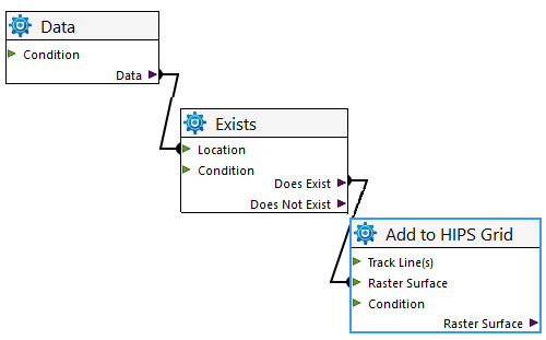
Logic / Conditional | A specific single tool type in the model that performs a logic operation, e.g. Exists | For example, an “Exists” logic tool- the output ports can be Does exist or Does not exist. |
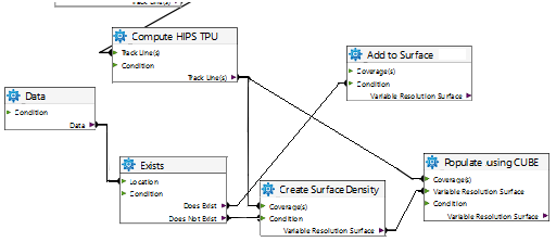
Model | A group of tools and their associated properties, linked in such a way to perform a task | |
Connector | A line drawn from tool to tool to show how one function connects to the other. Connectors will not attach Input to Input or Output to output. | For example, a line from an output port labelled Track Line(s) to a Coverage input port which indicates the output data will contribute to the coverage. |
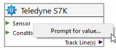
Prompt | Setting an Input, output or property from a tool as a prompt, causes that value to appear when running the model, allowing the user to enter a specific value each time the model is run. |
|
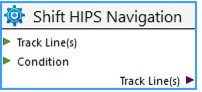
Port | Linkage points on a tool | Every tool have four different types of ports: input, output, condition and options. |
Condition port | A port that will only allow the tool to run if the condition is met. For example, Add to HIPS Grid will only run if the data file being checked meets the condition “Does Exist”. | |
| ||
Input / Output | Functions on a tool that generally specify data input and output resources. A tool can have multiple inputs if necessary, but only a single output. | For example, Track Line as input and a Merged track line as output. |
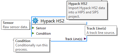
Screen tip | Descriptive box appears when cursor rests over various parts of a tool.
| |