The second step in the Sounding Selection Wizard is used to define the settings for the density of the selected soundings.
Interface
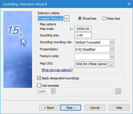
Step 2 of the Sounding Selection wizard is shown below.
Option | Description |
Suppression type | The type of sounding suppression that will be performed. The options are: • Radius: only the shoal- or deep-biased soundings within a set distance are written to the feature layer. • Overplot Removal: suppresses certain soundings in a dense set of soundings so the dataset can be plotted at a certain scale without overplotting. Overplotting occurs when soundings overlap or are so close together that they are plotted on top of each other. Two soundings with depths of 11 and 22 might look like 1212 when overplotted. Overplot removal works by placing a buffer zone around each sounding, then suppressing either the deepest or shoalest soundings that overlap these buffer zones. The Map Options available will differ based on the selected suppression type. The Overplot Removal option is not available for database sources unless they have been opened locally. |
Suppression Bias | Specify whether the sounding selection will include the shoalest soundings or the deepest soundings when conflicts are encountered during suppression. For example, if shoal-bias is selected and two soundings are overlapped, the shoalest sounding will be selected. |
Map Options: Radius | When Radius is selected as the suppression type, the following options are displayed. |
Radius value representation | This field is used to define what the radius value represents. The value entered for the radius can be used as a specific number of metres between each sounding, or the number of millimetres between soundings at map scale. If using map scale, you must specify the scale value. 1. Select a radius representation option. 2. If using map scale, enter the scale value. |
Radius value | The radius value can be defined by entering a single value or by referencing a radius table file. A radius table is a text file that sets the minimum suppression radius between soundings for various depth ranges. Each depth range can contain its own radius value. The table contains three columns: • minimum depth of the range • maximum depth of the range • suppression radius for the depth range. Each table entry should end with a single carriage return. Do not include any returns on or after the last entry at the end of the radius table file. 1. Select an option for defining the radius value. 2. Depending on the option selected, either enter a radius value or click the browse button (...) and navigate to an appropriate radius table file. |
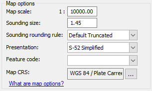
Map Options: Overplot Removal | When Overplot Removal is selected as the suppression type, the following options are displayed. The “What are map options?” text at the bottom of this section displays a tooltip with a brief explanation of the options in this section. Hover the mouse cursor over the text to view the information. |
Map scale | The scale at which the soundings should not overlap. |
Sounding size | The physical height of sounding symbols in the display, measured in millimetres at map scale. |
Sounding rounding rule | The rule for rounding sounding values for which the soundings should not overlap. For a brief description of the rules available, see the CARIS Support Files Guide, Sounding Rounding. |
Presentation | The presentation library with which to display the soundings to avoid overlap. |
Feature code | The feature code with which to display the soundings to avoid overlap. Feature codes correspond to detailed displayed settings for specific uses of feature objects. Feature codes are defined in the ih_master.txt file, which is found in the system folder of the installation directory. C:\Program Files\CARIS\<application>\<version>\system\CARISConfig Refer to the CARIS Support Files Guide for more information on the master file. |
Map CRS | The coordinate reference system (CRS) to apply to the soundings in the output file to avoid overlap in the display. The CRS of the output feature layer is selected by default. 1. Click the browse button (...) to launch the Select Coordinate Reference System dialog box and select a CRS to use for displaying the resulting soundings. |
Apply designated soundings | Select this option to ensure that priority is given to designated soundings during sounding selection. When the switch is off, designated soundings are processed with all other soundings, without special consideration for selection. When the switch is on, designated soundings are processed first, and then the remaining, non-designated soundings are processed. The non-designated data cannot suppress a designated sounding. |
Use template | Load or create a template file containing settings for performing a sounding selection. If creating a file with this option, when the wizard is finished it will create a sounding selection template (.csst) file containing all of the settings selected in the wizard. This file can then be loaded during future sounding selections to automatically define all of the settings in the wizard. 1. Click the Use template check box to enable to option. 2. Expand the drop-down list and choose whether to Load or Save the template file. 3. Click the browse button (...) to either navigate to an existing template file or specify a name and location for the new template file. |
Procedure
1. Select the suppression type to be applied and choose whether to use a Shoal bias or a Deep bias.
2. Define the Map options for the selected sounding suppression type.
3. [Optional] Enable the Apply designated soundings option.
4. [Optional] Select the Use template option.
5. If using the template option, choose whether to load or save a template file and then browse to the file location and select or enter a file name.
6. Click Next.