An alignment has a start position (X, Y) and an end position (X, Y).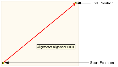
An alignment is a line with a defined direction. The line can be:
• a straight line (defined by two end points and a direction);
• an arc (defined by two end points, a centre point, and a direction); or
• a compound alignment containing any number of straight and curved alignments.
Alignments are used to identify the location of points. For example, stations are defined as being a certain distance along an alignment, and surfaces can be defined by points specified as being a certain distance from the ends of an alignment.
An alignment has a start position (X, Y) and an end position (X, Y).
In a straight alignment, the start position (StartX, StartY) represents the origin of the alignment, and the end position (EndX, EndY) indicates the direction of the y-axis.
In a curved alignment, the first two points created are used as the end points for the alignment. The third point creates the centre (radius) point for the arc based on the distance and location of the point in relation to the end points. The type of curve to apply to the alignment, either clockwise or counter-clockwise, is manually selected by the user. The following table shows the curved alignment types available based on the direction of the alignment and the position of the centre point.
Centre point... | Clockwise (CW) | Counter-clockwise (CCW) |
Above end points |
|
|
Below end points |
|
|
Using the Chains and Offsets feature, you can specify the location of a point in relation to the alignment. The chain represents the distance along the alignment and the offset represents the distance along the linear geometry perpendicular to the alignment.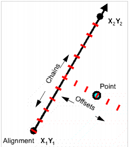
For example, a point with a chain of 0 and an offset of 100 is located 100 units (the Distance unit in Options > Display Units) from the start point of the alignment.
A point:
• referenced to a compound alignment; and,
• positioned in a non-overlapping zone of that alignment,
cannot be represented just by the chains and offsets of the compound alignment. In this case a hard turn angle is used to represent the point.
The following example shows the angle for a point referenced to a compound alignment before and after the point is moved into a non-overlapping zone of that alignment.
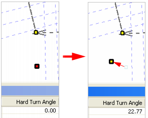
The hard turn angle is required in order to uniquely define points that are referenced to, and positioned in a non-overlapping zone of, a compound alignment.
Typically, a series of alignments creates a continuous linear geometry; however, it is possible to create broken alignments, as shown in the following illustration.
When a series of alignments are broken, as shown above, the chains must remain sequential. For example, if the first alignment in a compound alignment spans chain 0 to 1000, then the second alignment must have a start chain of 1000, regardless of the real-world coordinates.
See New Alignment Features for information on creating alignments.