For example, for calibrating navigation time error, rotate the subset so that the bounding box is parallel to the along-track direction. 
Calibration compares pairs of lines, surveyed under specific conditions.
In Subset Editor, the subset should be drawn either parallel or perpendicular to the calibration lines, depending on sensor values being examined, as follows:
Sensor |
|
Navigation Time Error | Performed on sets of two coincident lines, run at different velocities, over sloping terrain or a conspicuous topographic feature. Align the subset along track so you can view a profile of the two centre beams. |
Transducer pitch offset | Performed on sets of two coincident lines, run at the same velocity, in opposite directions, over sloping terrain or a conspicuous object. If data is from a dual-head transducer system, the error may be different between port and starboard transducers., Align the subset along track so you can view a profile of the centre beams. |
Transducer azimuth (Yaw) offset | Performed on sets of two lines, run over a conspicuous topographic feature. If data is from a dual-head transducer system, the error may be different between port and starboard transducers. Lines run in opposite directions, with the same outer beams crossing the feature. Align the subset along track so you can view a profile of the same outer beams for both lines. |
Transducer roll offset | The line pattern to detect the roll errors of a dual-head transducer is different from a single-head system, so error for each transducer must be resolved separately. Calibration is performed on sets of lines, offset by half the swath width, run over flat terrain. The centre line is run in the opposite direction to the offset lines, to allow for port and starboard swaths to be compared independently. Align the subset across track, to view a profile of individual swaths. The 2D slice should focus on an seabed area that appears flat For single-head transducer configuration, the lines can be coincident rather than offset. |
Procedure
Determine which pair of lines to use for calibration. For example, to determine navigation time error, choose two coincident lines that have been run in the same direction, at different speeds.
1. Open Subset Editor.
2. In the Display window, draw the subset bounding box over a portion of the pair.
For example, for calibrating navigation time error, rotate the subset so that the bounding box is parallel to the along-track direction.
3. Load the subset of these lines.
Menu | Tools > Subset Editor > Load |
Tool |
|
The subset of the data displayed in the 2D and 3D windows.
To easily distinguish between the lines being calibrated:
4. Select the HIPS data layer in the Subset Editor window.
5. Select Line from the Attribute list.
6. Set Colours to the TrackLine option.
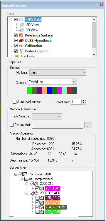
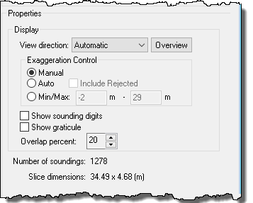
7. Select the 2D View layer and set the Display option for View direction to Automatic, and the Exaggeration Control to Auto.
8. Select the Calibration control layer to view the calibration tools.
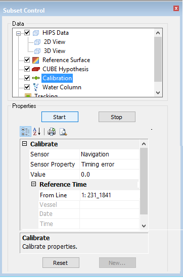
This will set both the 2D and 3D View into Calibration Mode.
Add a Sensor Date
Before running the actual calibration process, you can change or add a new sensor date/time entry to the HIPS Vessel file.
1. From the Sensor field in the calibration controls, select the sensor to be calibrated, for example, “Navigation”.
2. Click New... at the bottom of the control panel to open the New Date/Time dialog box.
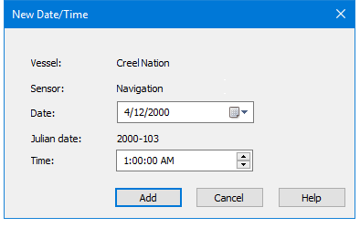
The vessel name and the name of the currently selected sensor are displayed. The Date field shows the date from the current Reference Time section.
3. Click the calendar in the Date field to set a different date.
The Julian date field will update to show the date you selected.
4. To update the time, either:
• Click Add to increase the time value by one hour, or
• Type a new time in the Time field.
Time value can also be set by selecting the hour, minute, second or AM/PM column and using either the scroll arrows in the field, or the keyboard arrow keys to adjust the value.
5. Click Add.
The new time is added to the HIPS Vessel file.
Apply Calibration
1. Select the sensor to be calibrated, for example, Navigation.
2. Select the sensor property to adjust, for example, Timing Error.
3. Click Start.
The 2D and 3D Views now displays a scale and slider controls with the data, as below:
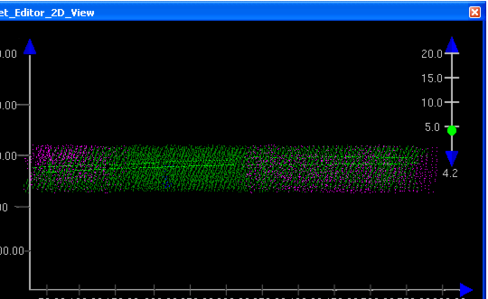
Use the controls to adjust the error values so that the two data lines are aligned. Use the vertical exaggeration slider or the compass control to view the data
Values can be adjusted:
• by sliding the green button along the ruler, or
• by clicking the blue arrowheads at the ends of the ruler, or
• by entering a value in the Value field in the Calibrate table.
As you adjust the slider, the Value field is updated. Also, if you type specific value in the field, the slider will move to that point on the ruler.
4. Click Stop when the desired value has been reached.
At this point you will be prompted to save the data.
5. Click Yes to save the new values to the HVF.
6. Repeat the process with other sensors.
When you finish calibration, you must Merge the line(s) again for the calibration adjustments to take effect.
During Calibration, data displayed in the Subset Editor views use the Merge functionality “on the fly” for display purposes only to visually show settings adjusted in the Calibration window. Any auxiliary sensor data already applied to the line, such as Refraction Coefficients or GPS Tide, will also be applied in the Calibration mode display. |
