Menu | Process > Compute TPU |
Tool |
|
Menu | Process > Compute TPU |
Tool |
|
Use the Compute TPU dialog box to either read all uncertainty values from the vessel file, or to read all from real-time data.
Alternatively, the Custom option enables you to set the uncertainty source for each component that contributes to the TPU computation. For example, Position error could be set to read from the vessel, while Roll and Pitch could be set to use real-time data, and a static value is set for Tide error.
TPU can be applied to a selection of lines or to the entire project, using settings in the Input Source field. The Ship Track Lines layer must be active to compute TPU.
If “Realtime” is specified and real-time sources are not found, Compute TPU will default back to the vessel file, and if static sources are not found there, TPU will use a value of “0” for that component.
If you choose “Realtime” as the uncertainty source configuration, and Delayed Heave RMS has been loaded (using the Import Auxiliary Data command), Compute TPU will use the Delayed Heave RMS data loaded with Import Auxiliary Data and override the Vertical RMS values in the source files. If you choose “Vessel” or “Custom” this doesn't apply. |
See also Sources of Uncertainty Data.
Interface
The Compute TPU command uses this dialog box:
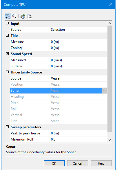
Option | Description |
Input | |
Source | If there is no data selected, the Source field displays “All Track Lines”. TPU will be applied to the entire project. If you have data selected, the Source field will display “Selection”. Selecting “Track Lines” will apply TPU to the lines open in the project. |
Tide. | Enter the vertical uncertainty values due to tide. These will be applied to all lines being processed |
Measure | The uncertainty value for the tide station. It is equivalent to the standard deviation of the Tide Gauge measurements. |
Zoning | The vertical uncertainty value in range calculation for a tide zone file. (HIPS does not model the TPU for the tide zone. Instead a single user-defined single value may be used here.) |
Sound Speed | The error offsets for Sound Speed Values. |
Measured | The offset value used in computing range error to compensate for inaccuracies in SVP measurements. |
Surface | The offset value is used to account for errors in surface sound speed measurements that alter the beam angle. This parameter is only applicable to systems that require accurate surface sound speed measurements. |
Uncertainty Source | Designate the uncertainty source for all components as either “Vessel” or “RealTime”, or set a “Custom” source for each individual component. |
Source | Set the sources for uncertainty data: • If Source is set to “Vessel”: all individual source fields are set to “Vessel” (read-only). • Selecting “Vessel” will ignore RMS data and use vessel settings. • If Source is set to “Realtime”: all individual sources are set to “Realtime” (read-only). • Selecting “Realtime” will use previously loaded Down/Heave RMS data If “Custom” is selected, individual sources may be set as follows. • “Vessel” or “Realtime” can be set as the source of the uncertainty values for: • Position • Sonar • Pitch • Heading • Roll The source of Vertical uncertainty values can be set to: • Vessel • Realtime Heave (Vertical RMS -GPS Height RMS/Heave RMS) • Delayed Heave (Delayed Heave RMS) The source of Tide uncertainty values source can be set to • Static (use values as set in the Measure or Zoning fields) • Realtime (from tide error files) |
Sweep parameters | Enter transducer motion offsets for sweep surveys |
Peak to peak heave | Enter the uncertainty value for the estimated observed heave of the transducer boom |
Maximum Roll | Enter the Roll offset of the transducer boom |
Maximum Pitch | Enter the Pitch offset of the transducer boom. |
Procedure
1. [Optional]: Select a track line or lines in the Display window.
2. Select the Compute TPU command.
1. Select “All Track Lines” from the drop-down list.
2. Set the error sources and values to be applied.
3. Click OK to apply TPU to processed depths
The Output window will list the error sources that were applied.
A graphical view of the results can be seen in the TPU Analysis Window.
