Menu | Tools > Limits & Boundaries > Bisector Line |
Tool |
|
The Bisector Line tool, similar to the Median Line tool, is used to define the boundary between two adjacent or opposing areas. This tool may be used instead of the Median Line tool if the user wants to manually specify the start point for the line, rather than have it generated automatically.
To use this tool, you must have a source line for each of the areas involved and a starting point.
• The source lines can be any line features that represent the coastal boundary of each area, such as baselines.
• The starting point defines the mid-point of the area to be bisected. This can be any digitized point/feature in the area, or an end point shared by the two source lines.
Prior to selecting the Bisector Line command, at least two of the input features (Source One, Source Two or Start Point) must be placed on their own feature layers, such as filter layers under the source data. This is needed because the input fields in the tool allow you to choose either the current superselection/selection, or a layer name. Since there are three inputs, the selection option is only feasible for one of the inputs. If a layer name is selected for the other two inputs, the application has no way of determining which feature is wanted on each selected layer. If the features exist as the only feature on each layer, the application will automatically select the correct feature for each input field. See the Create Layer by Attribute Value topic for more information on creating filtered layers.
If the start point is a shared vertex between the source lines, it will be selected automatically by the application and no changes are required. In this situation, only one of the source lines needs to be placed on its own feature layer.
To create a bisector line:
1. [Optional] Select an input feature in the Display, if necessary.
2. Select the Bisector Line command.
Menu | Tools > Limits & Boundaries > Bisector Line |
Tool |
|
The Bisector Line dialog box is displayed.
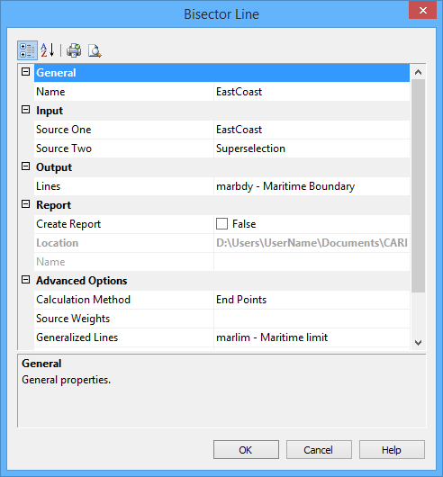
The following table describes the options available.
Group | Option | Description |
General | Name | The name of the layer on which the bisector line will be created. Select an option from the drop-down list. |
Input | Source One | The first source feature to use for the calculation. Select Superselection or Selection from the list if using a feature selected in the Display window, otherwise select the layer containing the feature to be used. |
Source Two | The second source feature to use for the calculation. Select Superselection or Selection from the list if using a feature selected in the Display window, otherwise select the layer containing the feature to be used. | |
Output | Lines | The object acronym and attribute values to be assigned to the resulting bisector line. The list contains the following options: • A list of recent objects, if any: Select an entry to reuse a previous object. • Template: Select this to define the feature acronym and attributes using a predefined template. This will launch the Select Template dialog box, from which you select a template, if any are available. • Objects: Select this to launch the Select Object dialog box from which you can manually select an acronym and define the attribute values. |
Report | Create Report | Select this option to generate a text file report of the coordinates of the contributing points from the source lines. |
Location | The location in which to create the report file. By default, the report is saved in the folder: C:\Users\<username>\Documents\CARIS\BASE Editor\<version\Bisector Line\ This can be changed by clicking the Browse button (...) and selecting a new location. This location will be remembered the next time the tool is launched. | |
Name | The name to assign to the report file. Enter a value in the field. | |
Advanced Options | Calculation Method | For the calculation of the bisector line, only two points in the source lines will be used, the start and end points. If the lines have more than two points, calculations will be done to create generalized lines from the source lines. These new lines will be created on the output layer selected for the bisector line and will be used to determine the area to be bisected. There are two available methods for calculating the generalized lines: • End Points: This method will calculate a straight line for each of the source lines, connecting their start and end points. • Best Fit: This method will calculate a straight line that best fits all of the points in the line, beginning at the start point. Using this method, the generalized lines will not necessarily end at the end points of the source lines. Select a method from the drop-down list. |
Source Weights | Weight the sources in the form of One:Two if one of the adjacent/opposing areas should be allotted more than half of the area being bisected. | |
Generalized Lines | The object acronym and attribute values to be assigned to the generalized lines. The list contains the following options: • A list of recent objects, if any: Select an entry to reuse a previous object. • Template: Select this to define the feature acronym and attributes using a predefined template. This will launch the Select Template dialog box, from which you select a template, if any are available. • Objects: Select this to launch the Select Object dialog box from which you can manually select an acronym and define the attribute values. Generalized lines will only be created if the source lines each contain more than two points. | |
Length | The length of the bisector line, extending from the start point. Because projected and geodetic measurements are not equivalent, the length of the line will be affected by the selected output Type. | |
Type | The measurement type to use for projecting the bisector line. The options include Loxodrome and Geodesic. This setting will override the Measurements Reference setting in the Display Units tab in Options, however, the Options setting will be used when calculating future measurements of the line. | |
Advanced Options (cont.) | Reverse Direction | Reverse the direction in which the bisector line is created. By default, the line begins at the start point and builds towards the ends of the source lines where the distance between the lines is the widest. |
Start Point | The feature to use as the start point for the line. If using a shared vertex, this field does not need to be completed; the vertex will be selected automatically when nothing is specified. |
Any options defined will be remembered the next time to tool is launched.
3. Define any necessary options.
4. Click OK.
The bisector line is drawn, along with any generalized lines that may have been needed. If the Report option was enabled, a text file is created in the location specified, containing the coordinates of the contributing points.
