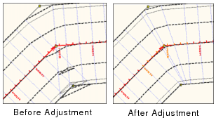
By default, profiles are perpendicular to the alignment at a given station. However, if a template has points of intersection, this can cause profiles to overlap. To avoid this, you can create non-perpendicular profiles by adjusting the angles of the profiles.
To define adjustment rules, perform the following steps:
1. Select the Adjustments option.
2. Click Add.
The Station Catalogue Adjustments dialog box is displayed.
First, you must define the range set of the alignment to which the rule will be applied. Each value in the Start chain and End chain fields must be measured from the start of the first alignment.
You can determine the chain of a profile by selecting the station it crosses. |
3. Type the Start chain value.
4. Type the End chain value.
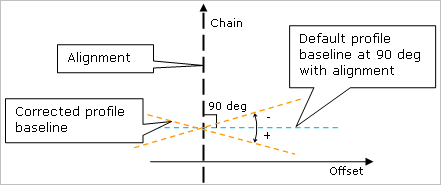
Next, you must define the correction to be made to the adjustment angle in terms of angle variation (degrees).
As shown below, clockwise corrections use positive values; counter‑clockwise corrections use negative values.
5. Do one of the following:
• To manually adjust the angle of the profile, type the angle of the profile at the start of the chain in the Start direction field. Then type the angle of the profile at the end of the chain in the End direction field. These values must be different from each other in order to place the profile at an angle.
• To have the correction automatically calculated by the application, select the Automatic option. This option adjusts all the profiles within the range set to correct all overlaps.
6. Click OK to close the dialog box and make the adjustment.
7. Repeat Steps 2 through 6 until all required profile adjustments are corrected.
The Display window refreshes to show the corrected profiles after each adjustment is completed.