The fourth step in the Import Wizard is used to define the output settings for the resulting coverage.
Interface
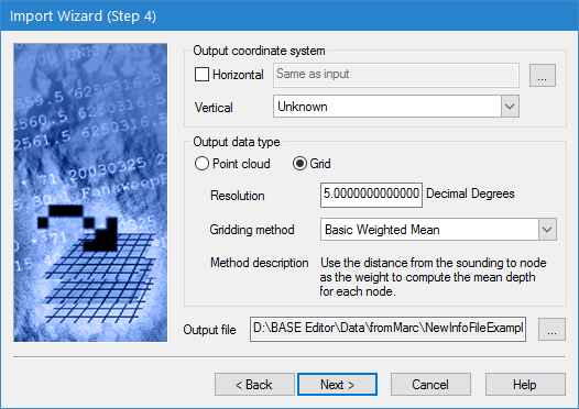
Step 4 of the Import Wizard is shown below.
Option | Description |
Output coordinate system | The output coordinate reference system (CRS) for the new coverage must consist of both a horizontal reference system and a vertical reference system. The horizontal reference system can be the same as the input coordinate system, however, you must choose the vertical reference system. Horizontal reference system selection is only required for data formats that do not include the projection in the source dataset. This includes the following formats: • CRS • HTF • HYD93 • NTX • XYZ If the appropriate output coordinate system is the same as the input coordinate system, leave the Horizontal check box empty; the field will read "Same as input". 1. Click the Horizontal check box to enable the field and then click the browse button (...) to launch the Select Coordinate Reference System dialog box and select a CRS. 2. Select a Vertical reference system from the drop-down list. |
Output data type | Select the data format for the output coverage. The options include • Point cloud: This option is used when you want to import your data in point form. • Grid: This option is used when you want to import the data as a raster with sampling based on the specified resolution. If using this option, you must specify the Resolution and Gridding method for the resulting surface. |
Resolution | The spacing of nodes in the resulting raster surface. The smaller the resolution value, the greater the disk space required to save the surface. If you selected a Geographic (Lat/Lon) projection for the output coordinate system, the unit of measure changes from metres to degrees. You will need to convert your value in metres to degrees, for example, 5m is approximately 0.000045219 degrees. |
Gridding method | The gridding method to use to generate the resulting surface. The following gridding methods are available. • TPU Weighted Mean: Use the Total Propagated Uncertainty (TPU) values for the soundings in the source files to compute a TPU-weighted mean depth for each node. To use this option, the source dataset must contain TPU values. An error message will be displayed in the Output window during import if there is no uncertainty data in the source. • Basic Weighted Mean: Use the distance from the sounding to a node as the weight to compute the mean depth for each node. This is a standard inverse distance weighting algorithm based on the ratio of the distance from the node in the output surface to the input point to the resolution of the output surface. All points within a resolution of the node are considered, even if they are in different output grid cells. The default power of the weighting is 2. • Shoalest Depth: Find the shoalest sounding near the node and assign the depth to the node. • Shoalest Depth True Position: Find the shoalest sounding near the node and assign the depth to the node. The original position of the sounding is retained as additional attributes on the node. As you select a method in the list, a brief description of that method will be displayed in the Method description field. |
Output file | The name and location to assign to the output coverage. 1. Click the Output file browse button (...) to define a name and location for the file. |
Procedure
1. Define the Output coordinate system settings.
2. Select the data type for the output.
3. If generating a raster surface, specify a Resolution and select a Gridding method for the new surface.
4. Define the name and location for the Output file.
5. Click Next.