The Extraction command copies user-defined sections of data from surfac objects in the database to your local machine. The data to be extracted is defined using digitizing methods. Data will be extracted from all surfac objects that fall within the specified area.
The data to be extracted depends on the layer selected in the Layers window. If the database layer is selected, all data for all surfaces within the defined area will be extracted. If a filtered layer is selected, only the data in the filtered layer will be extracted.
For example, if you create a filter layer for all data collected by a specific survey vessel, then perform an extraction with that layer selected, only data from that vessel within the defined area will be extracted. See Query by Attribute Value for information on creating filtered layers.
1. In the Layers window, select the database query layer containing the data you want to extract.
2. Select the (Database) Extraction command.
Menu | Database > Extraction |
The cursor changes to indicate that you are in digitize mode.
3. Click the display to begin digitizing a bounding box around the area from which you want to extract data.
4. Continue adding vertices until the area is surrounded.
5. To complete the bounding box, right-click and select Area Digitizer > Close Area.
The area is closed and the Database Extraction dialog box is displayed.
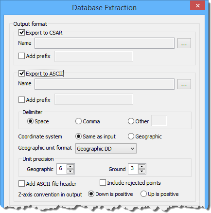
You can extract the data to CSAR files, ASCII files, or both.
• If you extract to CSAR, the result will be a new CSAR file for every surfac object that was within the selected area. The extents of each new surface will match the extents of the user-defined area.
• If you extract to ASCII, the result will be a new ASCII file for every surfac object that was within the selected area, again with the extents of the defined area.
6. Click the check boxes to enable the file formats you want to use.
As you select the check boxes, fields will be enabled for each format.
7. To specify a name and location for the new files, in the appropriate Name field, click the Browse (...) button.
The new files have the same names as the surfac objects from which they were extracted. For example, if one of the source surfac objects were named "My_Surface", then one of the resulting files would also be called "My_Surface". To avoid accidentally over-writing an existing file, a prefix can added to the file name during extraction, creating a unique name.
8. [Optional] To enable Add prefix, select the check box for the option.
9. [Optional] Enter the text you want added to the file name in the text entry field.
If you are extracting to CSAR, go to step 18. If you are extracting to ASCII, continue with the next step.
Delimiters are used to separate columns of data in a text file, such as ASCII, making it simpler to read. In addition to spaces and commas, you can use underscores, semi-colons, colons and any alpha-numeric character as a delimiter.
Punctuation marks are usually the better choice because letters and numbers can be difficult to distinguish from the data. |
10. Select a Delimiter option.
11. If you chose Other, in the text entry field, type a character.
You can apply the input coordinate system to the extracted file, or you can use Geographic.
12. Select a Coordinate system option.
For a Geographic coordinate system, you must specify the format for the coordinates.
13. From the Geographic unit format list, select an option.
Regardless of the type of coordinate system being used, you must specify the unit precision to use when displaying coordinates. This controls the number of decimal places in the values.
14. In the appropriate Unit precision field, use the up and down arrows to select a precision value.
The Add ASCII file header option creates column headings in the ASCII file for each of the attributes present in the extracted surfaces. If this option is not selected, no column headings will be present in the resulting file(s).
15. [Optional] To enable Add ASCII file header, click the check box for the option.
By default, rejected points are not included when exporting data. The Include rejected points option allows you to include these points if they exist in the selected area.
16. [Optional] To enable Include rejected points, click the check box for the option.
For the extracted data, the Z-axis convention output setting determines which direction for the data, down or up, is positive.
17. For Z-axis convention output, select an option.
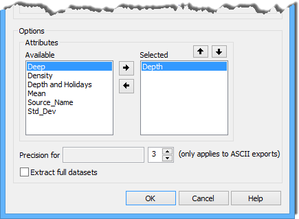
You do not have to extract all attributes present in the selected surfaces. The Attributes field lets you select the attributes to include in the extract.
18. Select an attribute in the Available list and, to move it into the Selected list, click the Add (right-arrow) button.
19. Repeat step 18 until all desired attributes are selected.
The primary Z layer (for example, Depth or Height) is required and cannot be removed from the Selected list. |
If exporting to an ASCII file, you can control the order of the attribute columns in the resulting file by changing the order of the attributes in the Selected list.
20. [Optional] Select an attribute in the Selected list, then click the Move (up or down arrow) button.
21. [Optional] To remove an attribute from the Selected list and move it back to the Available list, highlight the attribute and click the Remove (left-arrow) button.
You can also define the precision with which the attribute values will be extracted. This determines the number of decimal places in the attribute values.
22. To add an attribute from the Selected list to the Precision field, Double-click.
23. Use the Precision arrows or the number-pad of the keyboard to select or enter a value.
24. [Optional] Click the check box to enable the Extract full datasets option to extract the entire surface rather than the defined area.
25. Click OK to perform the extraction.
A file is created in the specified directory for each surfac object within the defined area. The following is an example of an XML data file extracted from a database.
If any of the surfaces that fall within the defined area do not contain bathymetry, they will not be extracted. The Output window will display a message listing any surfaces that were excluded, and the start and end times for the process.