The Vertical Shift Surface dialog box is displayed.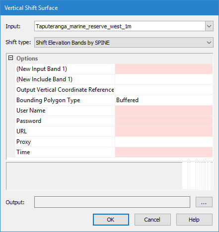
Menu | Tools > Surfaces > Vertical Shift |
Pop-up | Vertical Shift |
The Vertical Shift tool is used to apply a vertical shift to one or more layers (Depth, Height, etc.) of an existing raster surface or point cloud, to create an output surface with an increased or decreased Z value. There are numerous shift types available; this document describes the SPINE shift type. See Vertical Shift Surface for information on the other shift types.
The SPINE shift type is used to apply water level data to surfaces. This shift is achieved by connecting to the SPINE Water Level service provided by the Canadian Hydrographic Service (CHS). Requests are sent to the service for the water level values of specific sets of data points at specific times. Data is then returned for the requested points and times and applied to the matching points in the selected surface.
If your network is using a firewall, ensure that your Connection proxy settings are defined in Options before attempting to connect to the service. |
This shift type is only available if the SPINE module is enabled. See Modules for information about the modules in BASE Editor.
The Vertical Shift tool is also available through the ShiftElevationBands process in the CARIS Batch utility. Refer to the CARIS Batch Utility Reference Guide for more information on the command line tool. |
Procedure
To apply a vertical shift using the SPINE Water Level service:
1. Select the parent layer of the surface in the Layers window.
2. Select the Vertical Shift command.
The Vertical Shift Surface dialog box is displayed.
The Input field identifies the source surface to be shifted.
3. Select Input and choose a surface from the drop-down list.
4. Select Shift Elevation Bands by SPINE from the Shift type drop‑down list.
In the Options table, you define the output settings, the attribute bands to be included in the new surface and which of those bands will have their values shifted. The fields in the table differ based on the type of shift being performed.
Any layer with a Z value can be shifted. To have a band included in the new surface and have its values shifted, it must be selected as an Input Band. To have a band included in the new surface, but not shifted, it must be selected as an Include Band.
If a computed layer is included in the shifted surface, that layer will lose its dynamic status and will no longer be affected by changes to the primary elevation layer. |
5. Select the New Input Band field and select a band from the drop-down list.
Each time that a band is selected, a new line will be added to the table to select additional bands.
6. [Optional] Repeat step 5 for each layer you want included and shifted in the output surface.
7. [Optional] Select the New Include Band field and select a band from the drop-down list.
8. [Optional] Repeat step 7 for each layer you want included in the shifted surface with its original values.
A selected band can be removed if needed by selecting the appropriate row and either pressing the <Delete> key, or right‑clicking and selecting Undefined.
Input Band 1 cannot be removed because at least one Input Band must be selected. |
You have the option of selecting the vertical coordinate reference system for the output surface. The vertical component is added to the metadata of the surface, but does not apply any vertical transformations. The options available in the list are controlled by the Vertical Coordinate Reference System database. This list can be edited using the Reference System Editor tool. For more information, see Vertical Reference System Editor.
9. [Optional] Select an Output Vertical Coordinate Reference System option from the list.
The new surface can be created with a convex bounding polygon or with a buffered bounding polygon.
10. Select the Bounding Polygon Type.
Because SPINE is an online service, you must provide credentials to access the service.
11. Enter credentials for the SPINE service in the User name and Password fields.
The URL field is used to specify the URL of the service to which you want to connect, for example:
https://ws-shc.qc.dfo-mpo.gc.ca/spine
The URL can contain the port number if needed to access the service.
12. Enter the URL for the service.
Water level data differs depending on the time of day. To ensure that you have accurate data, you must apply data for the correct time period. The SPINE service, at the time this document was written, supports any future date/time up to one month in the future. The time of day, which defaults to 12:00:00 AM once a date is selected, must be entered in Universal Time Coordinated (UTC) format.
13. Enter or select the appropriate date and time of the data to be applied in the Time field.
14. Click the Output Browse (...) button to select a name and location for the new surface.
15. To finish, click OK.
A new surface is created and displayed in the Layers window. The Z values in the selected layers are shifted according to the selected method. The Lineage property for the new surface provides information on how the surface was created and details of the shift applied.