Menu | Tools > Engineering Analysis > Volumes > Comparative |
Tool |
|
The Comparative Volumes command allows you to compute the difference in volume above a model between two coverages. This option is useful in determining the amount of change that has happened; for example, the amount of material that has been dredged, or the amount of deformation that has occurred.
To calculate a comparative volume:
Menu | Tools > Engineering Analysis > Volumes > Comparative |
Tool |
|
1. Open the two surfaces for which you want to compare volumes.
2. Ensure that a TIN has been created for each.
3. [Optional] To use the Clipping by reference model surfaces option, open a reference model.
4. Select the Comparative Volumes command.
The Comparative Volumes dialog box is displayed. 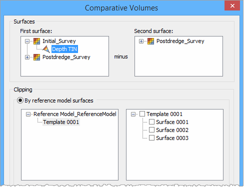
The First surface and Second surface fields are used to select the surfaces whose volumes will be compared. The Second surface will be subtracted from the First surface to calculate the difference.
Once a TIN is selected from the first list, only the TINs available for comparison are displayed in the second list. Note that the same TIN cannot be selected for both coverages, and that if one TIN is created from a raster surface gridded relative to a plane, the second TIN must have been created from another raster surface gridded relative to the same plane.
5. Expand a surface in each list and select the appropriate layer.
You can choose to use a reference model surface, an infinite plane or no clipping as the reference for volume calculation. When using a reference model surface, the Depth of the surface points and the Allowance Below attributes will be used. When using an infinite plane, you must specify the Depth of the plane and the Allowance value to be used. When the No clipping option is selected, a value below all the data is used.
To use a reference model surface, continue with the next step. Otherwise, to use an infinite plane, go to step 8. To use no clipping, go to step 12.
6. [Optional] Select the Clipping by reference model surfaces option.
7. In the list on the left, select the reference model template that contains the surface to be used.
The reference model surfaces available in the selected template will be listed in the box on the right.
8. Select a surface from the list on the right and go to step 13.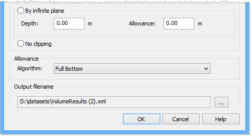
9. [Optional] Select the Clipping by infinite plane option.
You need to specify the Depth and the Allowance for the plane. These values will be entered in the unit of measure currently selected in the Display Units options. Depth is the depth of the plane being used as a reference. Allowance is the available space below the plane.
10. Enter a Depth value for the Clipping by infinite plane option.
11. Enter an Allowance value for the Clipping by infinite plane option.
12. [Optional] Select the No clipping option.
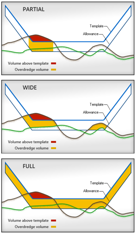
The Allowance Algorithm controls which method is used to calculate allowance volumes. You can opt not to apply an algorithm, or you can choose from one of the three algorithms provided:
• Partial Bottom: Calculates allowance volume only for the area of the model which has excess volume at the model depth.
• Wide Bottom: Calculates the allowance volume for the area of the model that has excess volume at the allowance depth/height. The allowance volume reflects the actual volume of material between the allowance depth/height and the model depth.
• Full Bottom: Calculates allowance volume for the entire model area regardless of the location of the material to remove.
If the Allowance value is zero, Overdredge volume will not be calculated and will also have a value of zero.
An example of each option is shown below.
13. Select an option from the Allowance Algorithm list.
The results of the calculation will be saved to an XML file that can be reopened at a later date. By default, the file will be saved to the Windows Temp folder the first time the command is run.
C:\Users\<username>\AppData\Local\Temp
If you choose to save to a different directory, that directory will be selected by default the next time the command is run.
14. Click the Output filename Browse (...) button to define a name and location for the results file.
15. Click OK to perform the calculation.
A progress bar will be displayed to track the progress of the calculation. As each selected surface is calculated, the results will be displayed in the Output window as raw data, meaning values have not been rounded or converted to the unit of measure being used in the application. If volume cannot be calculated for any reason, the name of the problematic surface will be output with an error message as the last entry in the Output window and the operation will stop.

When all calculations have finished, the results will be displayed in the following dialog box and saved to the specified XML file.
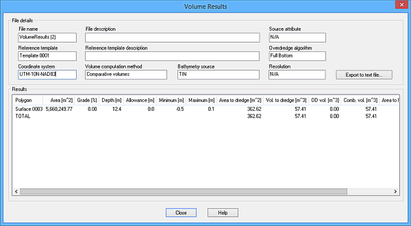
See Open Volume Results for more information on the results dialog box.
