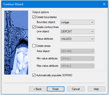
The Contour Wizard - Output Options dialog box is displayed.
In this dialog box, you define the object and attribute acronyms that will be used to create the features resulting from this procedure.
Boundary feature
A by-product of generating contours is a bounding polygon feature, which represents the inside and outside extent of the data used to derive the contour lines. By default, this feature object is created using the cvrage object acronym (Coverage Area); however, the possible acronyms are controlled by the catalogue of the feature layer being used to create the contours. If the cvrage acronym does not exist in the catalogue of the feature layer being used, the first acronym in the list will be selected instead. All open contours are connected to the boundary by connected nodes.
For the bMIO format, a metadata object such as M_QUAL can be used for the boundary object. |
1. Select an object acronym for the Boundary feature from the list.
You have the option of outputting either contour lines or areas, or both.
Create contour lines
To create contour lines:
2. Select the Create contour lines option.
If using the Bathy DataBASE catalogue, the Line object field is set to DEPCNT by default. The default acronym then selected for Value attribute when using DEPCNT is VALDCO.
3. Select a Line object option. This is the object acronym that will be used to create the contours.
4. Select a Value attribute option. This is the attribute acronym that will be used to assign values to the contours.
5. Click Finish to create the contour lines.
Create areas
To create areas:
6. Select the Create areas option.
If using the Bathy DataBASE catalogue, the Area object is set to DEPARE by default. The default settings for Min value and Max value when using DEPARE are DRVAL1 and DRVAL2, respectively.
7. Select an Area object option. This is the object acronym that will be used to create the areas.
8. Select a Min value attribute option. This is the attribute acronym that will be used to assign minimum values for the areas.
9. Select a Max value attribute option. This is the attribute acronym that will be used to assign maximum values for the areas.
10. [Optional] Select Automatically populate SORIND to automatically populate the source attribute value for the contours and areas.
11. Click Finish to create the contour areas.
The contour line and/ or depth area features are created and visible in the Display window.
If the output layer is using the Bathy DataBASE catalogue, any isolation type contours will have the Isolation Type (isotyp) attribute populated automatically.
This attribute defines whether the contour contains a shoal (shoaler than the surrounding elevation values) or a deep (deeper than the surrounding elevation values), or is unknown. This attribute can be used to filter the contour features or to resolve isolations when creating depth areas. The isotyp value for a selected contour can be updated in the Attributes window.
If the number of contours to be created exceeds the amount of memory available to complete the procedure, an error message will be displayed. You may be required to restart the application to clear your virtual memory if this happens. |
To view the new contour features:
1. Select the Refresh command.
Menu | View > Refresh |
Tool |
|
Key | <F5> |
The feature layer with the contour and area features can be saved to a HOB file using the File > Save command. You can change the colour display of the contours using the Properties for the feature layer.
