Menu | Tools > Surfaces > Render Raster |
The Render Raster command exports a single band from a raster surface to a raster image. This is accomplished by converting the values from the selected band into colours. The resulting image will have the same dimensions, coordinate reference system and geographic extent as the input.
The raster image is created in memory only and will be lost when the application or the layer is closed. If you wish to retain the new image file, it can be saved using the Save As command.
Related commands:
Interface
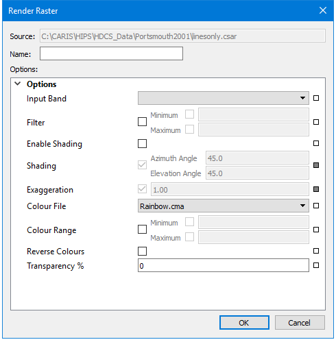
The Render Raster command uses the following dialog box.
Option | Description |
Source | The name and location of the input file. The Source is defined by the dataset that was selected at the time the command was initiated. This field cannot be changed. |
Name | The name to display for the new image band in the Layers window. |
Input Band | The band from the source dataset to be included in the rendered raster. |
Filter | Filter the input so only values in the input band within a specified range result in populated nodes in the output. Click the check box to enable the options. • Minimum - A number specifying the minimum value for the filter range. • Maximum - A number specifying the maximum value for the filter range. |
Enable Shading | Enable the sun shading options. |
Shading | The sun shading parameters used when rendering the raster. • Azimuth Angle - A number specifying the azimuth angle applied for sun shading in degrees. • Elevation Angle - A number specifying the elevation angle applied for shading in degrees. |
Exaggeration | A number specifying the multiplier for each band value. Only positive numbers are accepted. |
Colour File | The colour map file to use when rendering the raster. The list of available options is populated with all colour files present in the directory specified for the Colour Maps option in Tools > Options. |
Colour Range | The values that will map onto the first and last colours in the colour map. Click the check box to enable the Minimum and Maximum options. • Minimum - A number specifying the value that will map onto the first colour in the colour map. Click the check box to enable the option and enter a value. • Maximum - A number specifying the value that will map onto the last colour in the colour map. Click the check box to enable the option and enter a value. |
Reverse Colours | Enable this option to apply the colour map in the reverse order. |
Transparency % | A number specifying a percentage of transparency to apply to the image. |
Status Indicators
| Each option has a status indicator box beside the field. If the field has not been populated, or is populated with a default value, the box is coloured white. When a value is entered or a default value is changed, the status indicator box changes to grey to indicate it is no longer in the default state. If an option is mandatory, the status indicator box is coloured red. Fields can be returned to their default state by clicking the status indicator box and selecting “Reset”. |
Procedure
1. Select a dataset in the Layers window.
2. Select the Render Raster command.
The Render Raster dialog box is displayed.
3. Enter a Name for the resulting layer.
4. Define any necessary options.
5. Click OK.
A new raster image is added to the Layers window, populated and displayed according to the rendering settings.
Menu | File > Save As |
Pop-up | raster image > Save As (Layers window) |
6. If needed, select the Save As command to save the file for future use.
