
Dynamic cartography can apply navigation information to RECTRC lines. Examples include:
• Direction
• Minimum depth
• Bearing.
Dynamic cartography is useful for repositioning RECTRC symbology that is obscured by other features, such as lines or soundings.
Direction
Prerequisite: A RECTRC feature is available in a chart or workspace.
1. Select the RECTRC line.
2. Select the Edit Cartography command.
3. Right-click and select Line Symbol from the pop-up menu.
The linsym (line symbol) cartographic feature is added to the RECTRC line closest to where the mouse is clicked. This location is the default reference point.
4. In the Attributes window, enter values for these linsym attributes:
• ORIENT
• offset
• symcod (symbol code)
A symbol is drawn on the RECTRC line. The following image shows an IM10_2 arrow symbol on a RECTRC line with CATTRK=2.
While in cartography editing mode, the symbol can be moved in either direction along the line.
5. Position the mouse over the node in the symbol.
6. Press the mouse button and drag the symbol to a new location.
7. When finished, select the Edit Cartography command a second time.

Notice that the linsym feature was accessed from a pop-up menu. In the previous examples, cartographic features were accessed directly when the Edit Cartography command was applied or through the Create Annotation Link command.
This operation is controlled through the following instruction in DCRECTRC.xsl:
<AnnotationOption label="Line Symbol" class="linsym" areaPlacement="boundary"/> |
<AnnotationOptions/> contains three attributes:
• label is the text that will appear in the pop-up menu
• class points to the cartographic feature that will be applied
• areaPlacement is set to boundary which means, in this case, on the line.
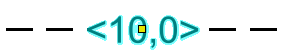
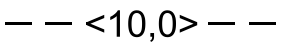
Depth
Prerequisite: A RECTRC line feature with an assigned DRVAL1 attribute includes a value.
1. Select the RECTRC line feature.
2. Select the Edit Cartography command.
3. Right-click on the RECTRC feature and select Depth from the pop-up menu.
A lintxt (line text) cartographic feature is created and linked to the RECTRC feature.
A depth value is drawn on the RECTRC line. The value is read from the DRVAL1 attribute.
While in cartography editing mode, the text can be moved in either direction along the line.
4. Position the mouse over the node in the text.
5. Press the mouse button and drag the text to a new location.
6. When finished select the Edit Cartography command a second time.
Again, the lintxt cartographic feature is accessed from a pop-up menu. The instructions for the Depth command is contained in DCRECTRC.xs:
<AnnotationOption label="Depth" class="lintxt" areaPlacement="boundary"> <InitialValues> <SetAttribute attribute="txtsiz" value="8"/> </InitialValues> </AnnotationOption> |
The attributes are the same for the linsym feature, except that a txtsiz (text size) attribute that is set to 8 points is now included. You can adjust this in DCRECTRC.xsl to a higher or lower value.
Bearing
Prerequisite: A RECTRC feature is available with an assigned OBJNAM value (for bearings).
1. Select the RECTRC line.
2. Select the Edit Cartography command.
3. Position the cursor over the line.
4. Right-click and select Name from the pop-up menu.
A cartographic namloc (name location) point feature is created and associated with the RECTRC feature. The namloc feature is added on the line.
5. While in cartography editing mode, position the cursor over the node on the bearing text.
6. Press and hold the mouse button and position the text above or below the RECTRC line.

7. Select the Edit Cartography command a second time.
The text is located at its new position

The nomloc cartographic feature is accessed from a pop-up menu. The instructions for the Name command is contained in DCRECTRC.xsl and output_from_XSLT.xml:
<AnnotationOption label="Name" class="namloc" areaPlacement="interior"> |