Menu | File > Export > Coverages > Image |
Tools | Render Raster Export Raster |
The Export Coverage to Image command exports a single numeric band from a raster surface to an image format. This is accomplished by first converting the values from the selected band into colours using the Render Raster process. The resulting image will have the same dimensions, coordinate reference system and geographic extent as the input. The resulting data is then converted to the selected image format using the Export Raster process.
The available formats include JPEG, PNG, GeoTIFF image and CSAR image. The options available for the export differ based on the selected output format.
This command is useful for converting a digital elevation model (DEM) in a supported raster surface format to an image format.
The processes used by this command are available in the Tools window. Also, process model files for each of the image formats are available in the following location:
C:\Program Files\CARIS\BASE Editor\<version>\system\Process Designer\Models\Export Band to Image
If this command will be run frequently with the same values, these files can be populated with predefined values in Process Designer and then run in the Run Process Model command, removing the need to manually define the options each time.
Interface
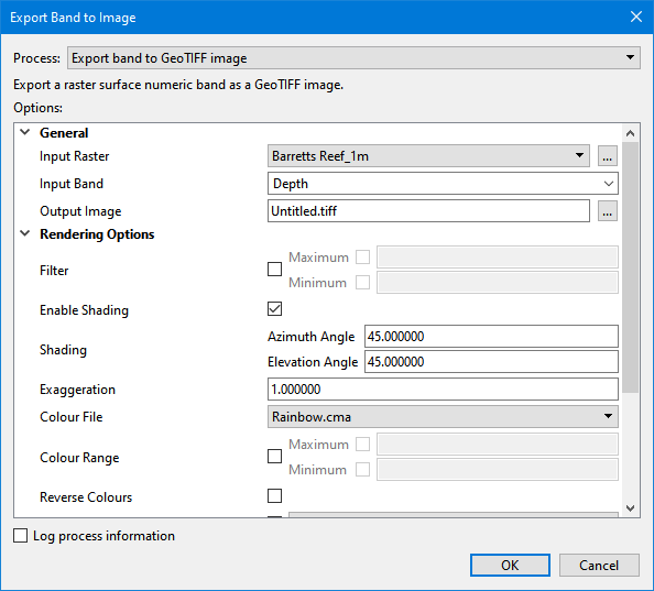
The Export Coverage to Image command uses the following dialog box.
Option | Description |
|---|---|
Process | The process that will be used to generate the output image file. The process to use depends on the desired output format. The options displayed in the dialog box will differ based on the process selected. |
General Options | |
Input Raster | The input raster surface. The drop-down list is populated with all raster surfaces currently open in the application. The browse button can also be used to navigate to a file not currently open. 1. Click the Browse button (...) to launch the Open File dialog box. 2. Navigate to the relevant file and click Open. |
Input Band | The band from the source surface containing the raster data to be converted to colour data in the output image file. |
Output Image | The name and location for the output file. 1. Click the Browse button (...) to launch the Save File dialog box. 2. Navigate to the relevant location for the file and type a file name. 3. Click Save. |
Rendering Options | |
Filter | Filter the input so only values in the input band within a specified range result in populated nodes in the output. Click the check box to enable the options. • Minimum - A number specifying the minimum value for the filter range. • Maximum - A number specifying the maximum value for the filter range. |
Enable Shading | Apply the sun shading options to the output image. |
Shading | The sun shading parameters used when rendering the raster. • Azimuth Angle - A number specifying the azimuth angle applied for sun shading in degrees. • Elevation Angle - A number specifying the elevation angle applied for shading in degrees. |
Exaggeration | A number specifying a multiplier to apply to each band value. Only positive numbers are accepted. |
Colour File | The colour map file to use when rendering the raster. The list of available options is populated with all colour files present in the directory specified for the Colour Maps option in Tools > Options. |
Colour Range | The values that will map onto the first and last colours in the colour map. • Minimum - A number specifying the value that will map onto the first colour in the colour map. • Maximum - A number specifying the value that will map onto the last colour in the colour map. 1. Click the check box to enable the Minimum and Maximum options. 2. Click the Minimum check box to enable the option and enter a value. 3. Click the Maximum check box to enable the option and enter a value. |
Reverse Colours | Enable this option to apply the colour map in the reverse order. |
Z-axis Convention | The Z-axis convention to apply to the data in the resulting image. This will affect how data is displayed and calculated. If this option is not enabled, the Z-axis Convention setting in Tools > Options will be used, which, by default, is Down is positive. 1. Click the check box to enable the drop-down list. 2. Select the relevant convention from the drop-down list. |
Transparency % | A number specifying a percentage of transparency to apply to the image. This option is not available for the Export band to JPEG process. |
GeoTIFF Image Options | |
Compression Type | The type of compression to apply to the output GeoTIFF image. This option is only available for the Export band to GeoTIFF image process. |
Create TFW | Enable this option to have georeferencing information written to a TFW file during export. This option is only available for the Export band to GeoTIFF image process. |
Procedure
1. Select the Export Coverage to Image command.
The Export Band to Image dialog box is displayed.
2. Select the Process for the desired output format.
3. Define all necessary options.
4. Click OK.
A new raster image is added to the Layers window, populated and displayed according to the rendering settings. A new file is created for the image in the specified location.