Lines are symbolized segment by segment, starting at the beginning of the line. A line segment is either:
• a portion of a point to point line between two consecutive significant points
• an entire stream line
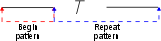
A symbolized line segment consists of two basic parts:
• the beginning of the line segment
• the repeating pattern within the line segment
For the special case when a line segment is smaller than a single pattern, the line is symbolized using a special short pattern.
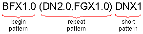
The line pattern definition has the following format:
begin_pattern (repeat_pattern) short_pattern
• begin_pattern is used to pattern the beginning of the line
• repeat_pattern is used to pattern the remainder of the line. These two parts together make up a full pattern.
• short_pattern is used only when a line segment is shorter than a full pattern.
The following is an example of a line pattern.
A pattern consists of one or more line patterning commands which may include qualifiers.
For the special case when a line segment is smaller than a single full pattern (the beginning pattern plus one complete repeat pattern), the line is symbolized using a special short pattern.
Dashes and Blanks
This group of commands generates dashes and blanks along a line. There are four dash and blank commands available:
DNXm.n | Normalized dashes, each one having a length of m.n inches. Normalized (also referred to as variable) means that the length of the dashes will be adjusted to make the pattern fit the line. How much the normalized dash can be adjusted is determined by the normalization factor (see the /NMF qualifier). |
DFXm.n | Dashes of fixed length, each having a length of m.n inches. Fixed length dashes are never adjusted to make a pattern fit the line. |
BNXm.n | Normalized blanks, each having a length of m.n inches. Normalized (sometimes referred to as variable) means that the length of the blanks will be adjusted to make the pattern fit the line. How much the normalized blank can be adjusted is determined by the normalization factor (see the /NMF qualifier). |
BFXm.n | Generates blanks of fixed length, each having a length of m.n inches. Fixed length blanks are never adjusted to make a pattern fit the line. |
Symbols
Several commands allows symbols to be added along a line, or to add successive symbols at a single point.
Ksymbol_id | Changes the symbol identifier of the current symbol in a pattern to the value specified by symbol_id. The corresponding symbol remains in effect until a new K command is encountered in the pattern. The symbol identifier is found in the symbol file records which describe the symbol. If the symbol has a feature code (i.e. it has a record in the master file), then the symbol identifier is equivalent to the feature code for the symbol. |
The symbol output commands are used to place symbols at specified locations on the line to be symbolized. Symbols are placed at the same angle as the line segment, unless the rotation qualifier (/ROT) is specified. The size of the symbols can be controlled using the /SIZ (size) qualifier.
The position of the symbol, relative to the location specified on the line, depends on the command used, as listed below:
SYO | The symbol is placed directly on the points in the line (opposite of SYM). |
SYM | The symbol is placed midway between the previous two points on the line (opposite of SYO) |
SYE | The symbol is placed midway between two points on the line and sized so that the edges of the symbol match, as in the case of scalloped lines. |
SYX | The symbol is placed at the end of the line only. This is useful when, for example, literal or shifted PAS segments are output, and symbols are to be placed at significant points along the line, rather than in a pattern. An example is a power line, where tower symbols are joined by solid line segments. It enables the line to be terminated with a tower symbol. |
Arcs and Circles
AG%a:z | Generate an arc from a to z. % can be: • O - the arc is centred around a point on the line. • M - the arc is centred midway between two points on the line. a and z are mathematical angles between 0 and 360 degrees and measured counter clockwise from the tangent to the line segment. The radius of the arc must be specified using the /RAD qualifier. If a radius is not specified, unexpected results will occur. You must use the colon to separate the two angular values. You cannot include blanks in the AG command. Positive or negative rotations are valid. |
To draw a full circle, specify the angle range as 0:360.
Arrows
ARn | Generates an arrow between the points of a point to point line. The arrow shaft width is controlled by the /OFF qualifier. Using blanks in the pattern command will cause the arrows to be altered in length. The arrowhead width and length are scaled relative to the shaft width. n is a case number, which can be: • 1: A straight arrow using two points. • 2: A bent arrow using three points. • 3: A curved arrow using three points. |
Arrows are generated on point to point lines only.
Other Commands
This section describes other line patterning commands that are available.
CD1 | The pattern which follows this command applies only to stream lines. The pattern is terminated by a CD3 command or the end of the pattern record. The CD1 command is used to pattern all stream lines bearing the feature code to which it is assigned, providing the stream line type is valid for the feature. A data type (e.g. stream line) is valid for a feature if the data type is specified in the data code (DC) field of the features corresponding master file main record. See Master File for a description of the master file and its components. |
CD3 | The pattern which follows the command applies only to point to point lines. The pattern is terminated by a CD1 command or the end of the pattern record. The CD3 command is used to pattern all point to point lines bearing the feature code to which it is assigned, providing the point to point line type is valid for the feature. The CD3 pattern will also be used to pattern stream type lines bearing the feature code to which the CD3 command is assigned, providing a CD1 pattern is absent for the feature, and the stream line feature type is valid for the feature. A data type (e.g. point to point line) is valid for a feature if the data type is specified in the data code (DC) field of the features corresponding master file main record. See Master File for a description of the master file and its components. |
DIS | Discard. Delete the remainder of a line after one full pattern has been created. This is sometimes used in conjunction with the LEX command to force the segments of point to point lines to always end with a full pattern. |
LEX:m.n | Line Extend Extend the segments of a point to point line so that each segment ends in a full line pattern. Each segment of the line will be internally extended by a length of m.n inches (for symbolization purposes only) to ensure that the minimum segment length is available. Some features do not have a true line pattern, since they do not repeat (i.e. only one pattern is created). Such features include tide and current arrows, traffic separation direction arrows, and calling in points. The length of these features may be subject to standards. The LEX command allows you to make sure there is enough line available to generate the feature. |
LSD:n | Literal Segment Draw. A literal segment is a segment of a point to point line which has not been symbolized. A segment is defined as the portion of a line between two consecutive points. This command leaves the nth segment unsymbolized (i.e. with no line patterning). If no value is specified, then segment 1 is assumed. For example, if a line has three literal segments, and its corresponding line pattern definition includes the command This command may appear anywhere in the pattern command and may contain up to 20 integers separated by colons. The segment number must be a positive integer. No warning is given if the line does not contain the specified segment(s). |
LSS:n | Literal Segment Skip This command does not leave the specified line segment(s) unsymbolized, it changes them to blank space. If no value is specified, then segment 1 is assumed. This command may appear anywhere in the pattern command and may contain up to 20 integers separated by colons. The segment must be specified as a positive integer. No warning is given if the line does not contain the specified segment(s). |
NCS | Do not constant size a line pattern. If the OPCS option is set, line patterns will be kept at a constant size, regardless of scale. If you create a pattern that you do not want to be kept at constant size, place the NCS command before any commands that include a size or line weight. NCS indicates that, even if OPCS is being used, the line pattern is to be drawn based on the scale of the file. To override the effect of the line weight in the main record in such a line pattern, each pattern command that would use a line weight should be explicitly given one. For example: NCSALTR 0 ID12 Track BK N DD 03 10 13 NCSALTR L0 NCS,DNx.055/lwt.01,(BNx.02/ NCSALTR L1 lwt.01,DNx.055/lwt.01), NCSALTR L2 DNx.01/lwt.01 |
PAn | Parallel lines. Generate one or two lines, parallel to the original, for both point to point and stream lines. The /OFF qualifier defines the distance between the original line and the newly generated line; the /LWT qualifier determines the line weight of the new line. (The lineweight of the original line is determined by the master file entry.) The PAS command must be used if the original line is to be retained. • PA1: One line to the right of the original line. • PA2: Two parallel lines, one on each side of the original line. • PA3: One line to the right of the original line and perpendiculars from the start and end of the new line to the original line. • PA4: Two parallel lines, one on each side of the original line, and perpendiculars from the start and end points of the new lines. It may be easier to decide which side of a line is the right if you imagine you are standing on the line and facing in the direction of digitization. |
PAS | Pass the Input Line. Passes both the unsymbolized and the symbolized feature.You can use the /OFF qualifier to shorten the line segments before they are output. This is useful for providing space for symbols at significant points on a line. |
PTE | Pattern to End The PTE command causes a pattern to continue to the end of the line, with no normalization. If the line ends in the middle of the pattern, the pattern will be truncated. As an example, take a pattern like the one illustrated. This has a begin pattern consisting of a dash and a repeat pattern consisting of spaces, a symbol, and a dash. With no PTE command, the pattern would look like this: The dashes and spaces are normalized to fit one begin pattern and two repeat patterns into the length of the line With a PTE command the dashes and spaces are drawn at the defined size (not normalized), and the final dash is truncated to fit. This fits one begin pattern, one complete repeat pattern and part of a second repeat pattern into the length of the line., |
[n;] | Sub-pattern. Patterns enclosed in square brackets are called sub-patterns and can be repeated n times. The semicolon is mandatory. Any pattern command may appear in the sub-pattern. You may specify several sub-patterns in a line pattern definition. |
TOL m.n | Line Angle Tolerance. This command allows you to alter the criteria by which a point is considered to be significant. A significant point is one which causes a line to deviate enough from its present course to warrant the start of a new line pattern. The default value for /TOL is |
NMF | Normalization factor. The NMF command allows you to control how much the adjustable length blanks (see the BN command) and dashes (see the DN command) in a pattern may be reduced to make the pattern fit a line segment. The default value is: 0.5.seg_length <= total_Fix + total_var*NMF • seg_length is the length of the line segment • total_fix is the total length covered by fixed pattern items • total_var is the total length covered by variable pattern items • NMF is the normalization factor For example, given: • the pattern • a line 2.5 inches long to pattern • an NMF value of 0.5
When the default NMF value of 0.5 is used, the total lengths specified in the variable dash (DNx) and variable blank (BNx) commands is factored by 0.5, meaning that the length of dashes and blanks can be varied by up to 50%. When NMF is 0.25, the dashes and blanks can be varied by up to 75%. If you wish to eliminate variable segments, set NMF to |